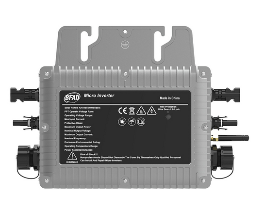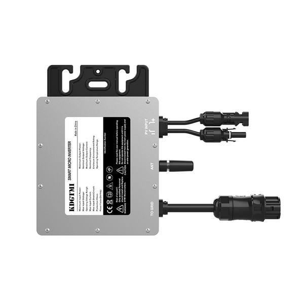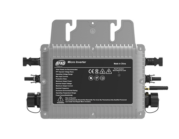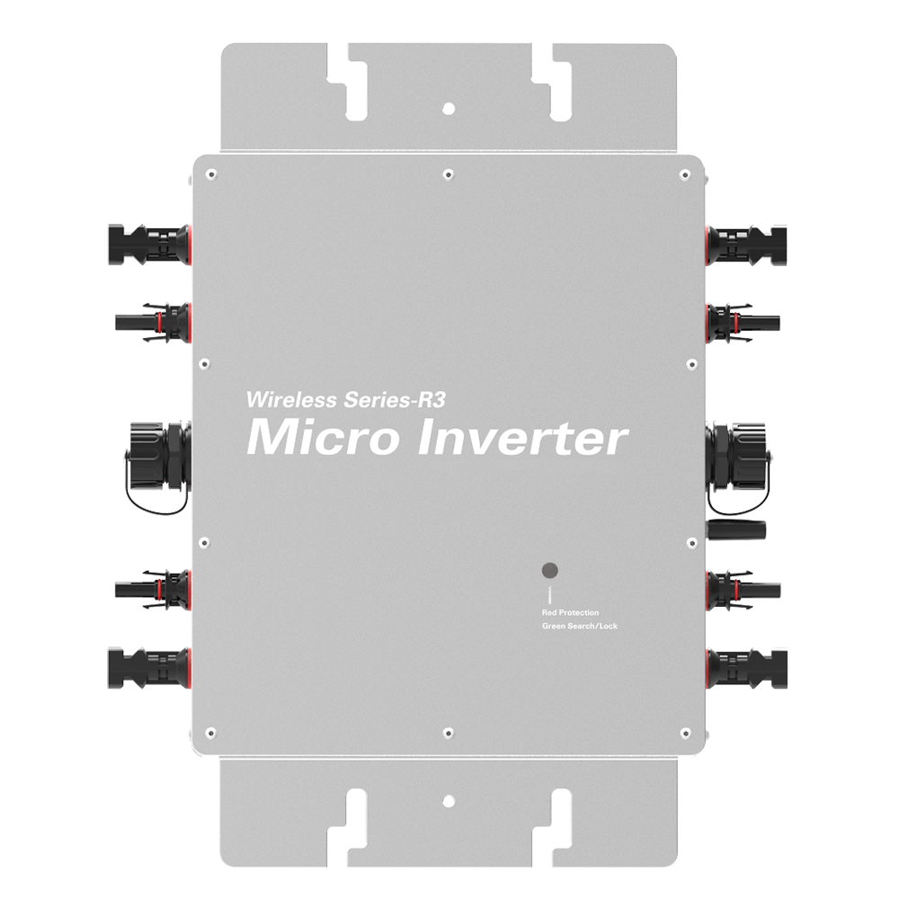
The four lights on the micro inverter usually represent the working state, the fault state, the output power and the communication state.
The first is the working state light, usually a green or blue light, indicating that the inverter is working normally and can normally convert direct current to AC power supply. When this light is on, it indicates that the inverter is operating normally and there is no fault or problem.
This is followed by a fault state light, usually a red or yellow light, indicating that the inverter has a fault or abnormal situation. When the light is on, it needs to be repaired and treated in time to ensure the normal operation and safe use of the system.
The third is the output power lamp, usually an orange or yellow light, indicating the current output power of the inverter. The working state and load of the inverter can be judged by the light on or off or blinking, and the operation of the system can be adjusted and optimized in time.
Finally, the communication status light, usually blue or green, indicates the communication status between the inverter and the monitoring system or other equipment. The normal lighting of this light can ensure the normal monitoring and operation of the inverter by the monitoring and control system, and ensure the stable operation and optimal management of the system.
Through the status of these four lights, users can easily understand the working condition of the inverter, discover and deal with problems in time, and ensure the safe operation and efficient use of the system. Therefore, it is very important to pay attention to the state of these lights in time.


